
Specifications and Requirements
Technical Details
- Nordic nRF9151*
- Microcontroller
- Arm® Cortex®-M33
- 247 EEMBC CoreMark score running from flash memory
- Data watchpoint and trace (DWT), embedded trace macrocell (ETM), and instrumentation trace macrocell (ITM)
- Serial wire debug (SWD)
- Trace port
- 1 MB flash
- 256 kB low leakage RAM
- Arm TrustZone®
- Arm CryptoCell™ 310
- Up to 4x SPI master/slave with EasyDMA
- Up to 4x I2C compatible two-wire master/slave with EasyDMA
- Up to 4x UART (CTS/RTS) with EasyDMA
- I2S with EasyDMA
- Digital microphone interface (PDM) with EasyDMA
- 4x pulse width modulator (PWM) unit with EasyDMA
- 12-bit, 200 ksps ADC with EasyDMA - eight configurable channels with programmable gain
- 3x 32-bit timer with counter mode
- 2x real-time counter (RTC)
- Programmable peripheral interconnect (PPI)
- 32 general purpose I/O pins
- Single supply voltage: 3.0 – 5.5 V
- All necessary clock sources integrated
- Package: 12.1 × 11.1 × 1.2 mm LGA
- LTE modem:
- Transceiver and baseband
- 3GPP LTE release 14 Cat-M1 compliant
- 3GPP LTE release 14 Cat-NB1 and Cat-NB2 compliant
- GPS receiver
- GPS L1 C/A supported
- QZSS L1 C/A supported
- RF transceiver for global coverage
- Power Class 3 up to 23 dBm output power
- Power Class 5 up to 20 dBm output power
- -108 dBm sensitivity (Cat-M1) for low band, -107 dBm for mid band
- Single 50 Ω antenna interface
- LTE band support in hardware:
- Cat-M1: B1, B2, B3, B4, B5, B8, B12, B13, B18, B19, B20, B25, B26, B28, B66, B85
- Cat-NB1/NB2: B1, B2, B3, B4, B5, B8, B12, B13, B17, B19, B20, B25, B26, B28, B65, B66, B85
- Supports SIM and eSIM with an ETSI TS 102 221 compatible UICC interface
- Power saving features: DRX, eDRX, PSM
- IP v4/v6 stack
- Secure socket (TLS/DTLS) API
- DECT NR+:
- NR+ band: 1, 2, 9, 22
- Supports 4FF Nano SIM and MFF2 footprint
- Microcontroller
- Raspberry Pi RP2040 as CMSIS-DAP programmer
- USB-C connection for USB-to-Serial and DFU
- External NOR Flash by Winbond
- 128mb (16MB) of space (4x nRF9160 Feather!)
- Max bus speed of 133MHz
- Standard SPI
- Power supply
- nPM1300 <1uA of quiesent current.
- Operating range 3.0 to 5.5V
- External LiPoly battery connection (JST SPH type)
- Programmer
- Onboard CMSIS-DAP
- Capable of interfacing with other Jlink and CMSIS-DAP based programmers with recovery fixture
- User I/O
- Standard feather form factor GPIOs (0.1“ pitch)
- 3x buttons (1 Reset, 1 General Purpose, 1 for RP2040 bootloader)
- 1x RGB LED driven by the nPM1300
- Antenna connections:
- 1x U.FL for combination LTE and GPS antenna
- Feather form factor
- 50.8mm x 22.86mm (2“ x 0.9“)
* nRF9151 tech specs provided from the nRF9151 Product Specification
Electrical
Here are the elctrical specifications for the nRF9151 Feather. Most of the specifications here are based on the nRF9151 Product Specification. You can get the latest version of the nRF9151 Product Specification here.
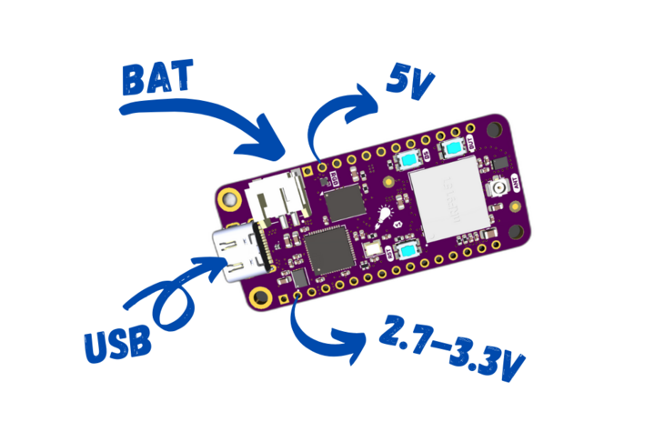
Board Supply
- Output voltage (VDDIO): 2.7-3.3V*
- Active sleep current < 10µA @ 2.7V
* nPM1300 is adjustable in firmware. Default power on voltage is 2.7V.
For more information, refer to the nPM1300 product specification.
External Power Supply
The nRF9151 Feather can be powered via battery or USB. See below for the specifics for each power source
USB Requirements
- Operating range: 5V ± 0.2V
- Current requirements: up to 1A
Battery Requirements
- Battery type: LiPoly or Primary Cell³
- Operating range: 2.8-5.5V
- Current/power rating: Able to support at least 2W of power
- Battery capacity: > 300mAH²
- Battery connector polarity: the battery polarity is important. This Feather board only supports Adafruit Feather compatible batteries. Note the wire color and orientation in the below picture:
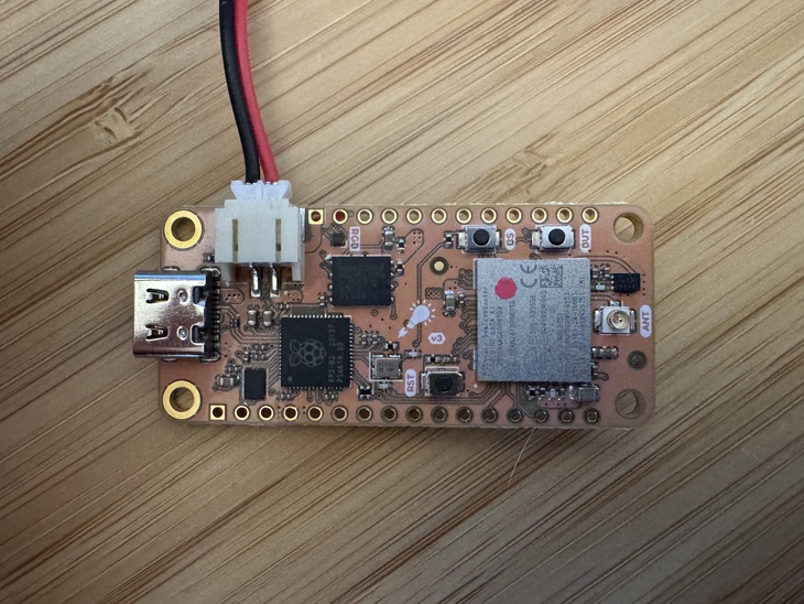
²Batteries below this capacity are not recommended nor supported due to the limited ability to provide enough current.
³The feather supports primary cells (alkaline and lithium) as long as they’re in the correct voltage range and charging is disabled on the nPM1300 PMIC
Temperature Range
Operational temperature range: -25°C to +85°C
Cellular Antenna
The nRF9151 Feather has been tested with these antennas. They’re chosen specifically to match the FCC requirements as indicated for the FCC grant of 2ANPO00NRF9151:
The maximum antenna gain for compliance with radiated power limits and RF exposure requirements is 9.0 dBi for LTE FDD 2/25 frequency band, 6.0 dBi for LTE FDD 4 frequency band, 7.1 dBi for LTE FDD 5/26 frequency band, 6.6 dBi for LTE FDD 12 frequency band, 6.9 dBi for LTE FDD 13 frequency band, 6.6 dBi for LTE FDD 17 frequency band, 6.0 dBi for LTE FDD 66 frequency band, 6.6 dBi for LTE FDD 85 frequency band.
Results:
LTE FDD 2/25: 5.1 dBi < 9.0 dBi → Compliant
LTE FDD 4: 5.1 dBi < 6.0 dBi → Compliant
LTE FDD 5/26: 6.3 dBi < 7.1 dBi → Compliant
LTE FDD 12: 4.9 dBi < 6.6 dBi → Compliant
LTE FDD 13: 4.9 dBi < 6.9 dBi → Compliant
LTE FDD 17: 4.9 dBi < 6.6 dBi → Compliant
LTE FDD 66: 5.1 dBi < 6.0 dBi → Compliant
LTE FDD 85: 4.9 dBi < 6.6 dBi → Compliant
| Part Number | Manufacturerer | Datasheet | Notes |
|---|---|---|---|
| ANT-LTE-RPC-UFL | TE Connectivity | Link | GPS/GNSS, Rigid |
Only tested antennas are supported.